Collaborative Robots
ISO/TS 15066 Force Limits: The Table That Decides Your Cell
The full biomechanical limits table from ISO/TS 15066 Annex A, with force, pressure, energy and speed values by body region, and what changed when ISO 10218 absorbed it in 2025.
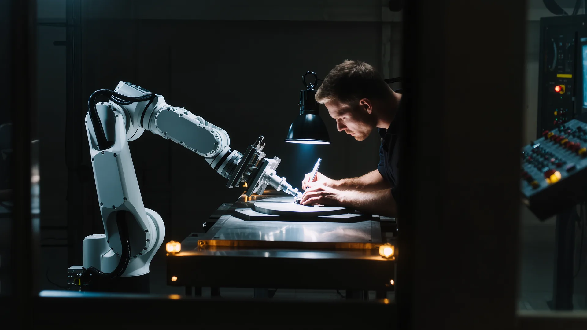
A collaborative robot may press against a human hand with 140 N in a clamping situation and up to 300 N/cm² at the fingertip, while the chest tolerates only 140 N and 120 N/cm² at the sternum. Contact with the face and skull is not permitted at all. Those numbers come from Annex A of ISO/TS 15066:2016, and they are the reason most cobot cells end up slower than the sales demo.
First, the status of the document
ISO/TS 15066:2016 was a technical specification, not a standard, and it no longer stands alone. When ISO 10218-1 and ISO 10218-2 were revised in February 2025, the power and force limiting content of the technical specification moved into ISO 10218-2:2025. The limit values were not relaxed. If a supplier still quotes "TS 15066 compliant", that is shorthand for the same numbers, now living in a different document.
Two contact cases are distinguished throughout, and mixing them up is the most common error in a validation report.
- Quasi-static contact is clamping. The body part cannot retreat, so the load persists. These are the base values in the table below.
- Transient contact is a free impact where the body part can recoil, typically lasting under 50 ms. Both the force and the pressure limit are multiplied by 2, except in the critical head zone where transient contact is simply not applicable.
The biomechanical limits table
Pressure limits are defined per specific body area; force limits apply to the whole body region. Both have to be evaluated, because one of them is always the binding constraint and it is not always the same one.
| Body region | Specific area | Pressure N/cm² | Force N |
|---|---|---|---|
| Skull and forehead | Middle of forehead | 130 | 130 |
| Skull and forehead | Temple | 110 | 130 |
| Face | Masticatory muscle | 110 | 65 |
| Neck | Neck muscle | 140 | 150 |
| Neck | Seventh neck vertebra | 210 | 150 |
| Back and shoulders | Shoulder joint | 160 | 210 |
| Back and shoulders | Fifth lumbar vertebra | 210 | 210 |
| Chest | Sternum | 120 | 140 |
| Chest | Pectoral muscle | 170 | 140 |
| Abdomen | Abdominal muscle | 140 | 110 |
| Pelvis | Pelvic bone | 210 | 180 |
| Upper arm and elbow | Deltoid muscle | 190 | 150 |
| Upper arm and elbow | Humerus | 220 | 150 |
| Lower arm and wrist | Radial bone | 190 | 160 |
| Lower arm and wrist | Forearm muscle | 180 | 160 |
| Lower arm and wrist | Arm nerve | 180 | 160 |
| Hand and fingers | Forefinger pad, dominant | 300 | 140 |
| Hand and fingers | Forefinger pad, non-dominant | 270 | 140 |
| Hand and fingers | Forefinger end joint, dominant | 280 | 140 |
| Hand and fingers | Forefinger end joint, non-dominant | 220 | 140 |
| Hand and fingers | Thenar eminence | 200 | 140 |
| Hand and fingers | Palm, dominant | 260 | 140 |
| Hand and fingers | Palm, non-dominant | 260 | 140 |
| Hand and fingers | Back of hand, dominant | 200 | 140 |
| Hand and fingers | Back of hand, non-dominant | 190 | 140 |
| Thigh and knee | Thigh muscle | 250 | 220 |
| Thigh and knee | Kneecap | 220 | 220 |
| Lower leg | Middle of shin | 220 | 130 |
| Lower leg | Calf muscle | 210 | 130 |
Where the numbers come from
The pressure values come from a pain-onset study conducted at the University of Mainz: 100 healthy adult subjects, 29 specific body areas, a flat metal test surface of 1.4 cm by 1.4 cm with a 2 mm edge radius, and the published figure is the 75th percentile of the recorded range. They mark the onset of pain, not the onset of injury.
The force values have a different origin. They were derived from an independent review of 188 sources and are calibrated to stay below severity 1 on the Abbreviated Injury Scale, which is a bruise. That difference matters when a report claims a cell is "safe" because it stayed under the force limit: the pressure limit may still have been exceeded, and pressure is what a fingertip feels.
Energy limits and the speed they imply
For transient contact the standard converts the limits into a transferable energy per body region, using the effective spring constant of that region. This is the step that turns a safety table into a velocity setting on the controller.
| Body region | Spring constant N/mm | Effective mass kg | Max energy J |
|---|---|---|---|
| Skull and forehead | 150 | 4.4 | 0.23 |
| Face | 75 | 4.4 | 0.11 |
| Neck | 50 | 1.2 | 0.84 |
| Back and shoulders | 35 | 40 | 2.5 |
| Chest | 25 | 40 | 1.6 |
| Abdomen | 10 | 40 | 2.4 |
| Pelvis | 25 | 40 | 2.6 |
| Upper arm and elbow | 30 | 3 | 1.5 |
| Lower arm and wrist | 40 | 2 | 1.3 |
| Hand and fingers | 75 | 0.6 | 0.49 |
| Thigh and knee | 50 | 75 | 1.9 |
| Lower leg | 60 | 75 | 0.52 |
Leg masses are set to full body weight, because a standing operator cannot recoil from a strike to the shin. The energy relation is E = F²max / 2k, and combining it with a two-body inelastic contact model gives the permissible relative speed. The worked example in Annex A, for a contact area of 1 cm², produces the numbers that most integrators actually need.
| Body region | 1 kg | 2 kg | 5 kg | 10 kg | 15 kg | 20 kg |
|---|---|---|---|---|---|---|
| Hand and finger | 2,400 | 2,200 | 2,000 | 2,000 | 2,000 | 1,900 |
| Lower arm | 2,200 | 1,800 | 1,500 | 1,400 | 1,400 | 1,300 |
| Upper arm | 2,400 | 1,900 | 1,500 | 1,400 | 1,300 | 1,300 |
| Abdomen | 2,900 | 2,100 | 1,400 | 1,000 | 870 | 780 |
| Pelvis | 2,700 | 1,900 | 1,300 | 930 | 800 | 720 |
| Upper leg | 2,000 | 1,400 | 920 | 670 | 560 | 500 |
| Lower leg | 1,700 | 1,200 | 800 | 580 | 490 | 440 |
| Shoulders | 1,700 | 1,200 | 790 | 590 | 500 | 450 |
| Chest | 1,500 | 1,100 | 700 | 520 | 440 | 400 |
Read the bottom right corner. A robot with 20 kg effective mass moving toward a chest is capped at 400 mm/s. The same robot toward a hand may run at 1,900 mm/s, almost five times faster. Cell layout, not controller tuning, is what decides which row applies to your cycle.
Validating in the real cell
Calculation is not evidence. Validation requires a measuring device with a spring element matched to the body region, placed at every reachable contact point, and the measurement has to capture the peak within the first milliseconds. Practical guidance from the field:
- Count the contact scenarios before quoting the job. A cell with 12 reachable points is typically a full day of measurement.
- Measure with the real workpiece fitted. A 2 kg part added to a 10 kg arm shifts the effective mass and every derived speed.
- Pressure fails before force in almost every clamping case. Increasing the contact area with padding is usually cheaper than reducing speed.
- The contact area assumption of 1 cm² in Table A.5 is an example, not a rule. A narrower edge produces lower permissible speeds.
Frequently asked questions
What is the maximum force a cobot may apply to a human?
It depends on the body region and the contact type. Quasi-static limits run from 65 N at the face to 220 N at the thigh, with 140 N at the hand and chest. Transient contact doubles those values, except in the head zone, where contact is not permitted at all.
Is ISO/TS 15066 still valid in 2026?
Its content is, its independent status is not. The February 2025 revision of ISO 10218 absorbed the power and force limiting requirements into ISO 10218-2:2025. The Annex A limit values themselves carried over unchanged.
What is the difference between quasi-static and transient contact?
Quasi-static contact is clamping, where the body part cannot move away and the load persists. Transient contact is a brief impact where the body part can recoil. Transient limits are twice the quasi-static values for both force and pressure.
Which limit binds first, force or pressure?
Usually pressure, and especially in clamping scenarios at the hand. The standard requires both to be evaluated. A large padded surface can satisfy the pressure limit while the force limit becomes the constraint; a sharp edge does the opposite.
Do the limits mean a person will not be injured?
The pressure values mark the onset of pain in a 75th-percentile sample of 100 healthy adults, not an injury threshold. The force values are set below severity 1 on the Abbreviated Injury Scale, meaning a bruise. Neither promises that a specific person in a specific posture is unharmed, which is why the risk assessment still governs.
How fast may a collaborative robot move?
There is no single number. Annex A gives worked speed limits from 2,900 mm/s toward an abdomen at 1 kg effective mass down to 400 mm/s toward a chest at 20 kg, all for a 1 cm² contact area. The separate 250 mm/s limit in ISO 10218-1 applies to manual reduced-speed mode and is a different rule.
Sources
- ISO/TS 15066:2016(E), Annex A, Tables A.1 to A.5All force, pressure, spring constant, energy and speed values in this article
- ISO 10218-1:2025, Robotics, Safety requirements, Part 1International Organization for Standardization, published February 2025
- Updated ISO 10218: frequently asked questionsAssociation for Advancing Automation, on the absorption of ISO/TS 15066
- Collaborative robot systems, information sheet 080German Social Accident Insurance (DGUV), practical validation guidance